
Get Support
123-456-789-10
Solenoid Force Calculation Explained for Engineers
-
 By: solenoids
- Aug 24, 2026
- 98 Visit
Whether you are designing a high-speed automotive latching actuator, an automated valve for fluidic control, or a low-power electronic lock, calculated mechanical output is the foundation of electromagnetic engineering. For design teams across global technology hubs—from Silicon Valley and Detroit to Munich, Tokyo, and Seoul—accurately determining the solenoid force-stroke relationship eliminates costly design iterations and prevents early coil burnout.
At Nextcore Electronic Co., Ltd., we assist R&D engineers worldwide in translating theoretical electromagnetic calculations into optimized, custom-manufactured solenoids, solenoid valves, and precision solenoid coils.
The electromagnetic attraction force generated by a linear DC solenoid at a given air gap can be derived from Maxwell’s stress tensor equation in magnetic circuits:
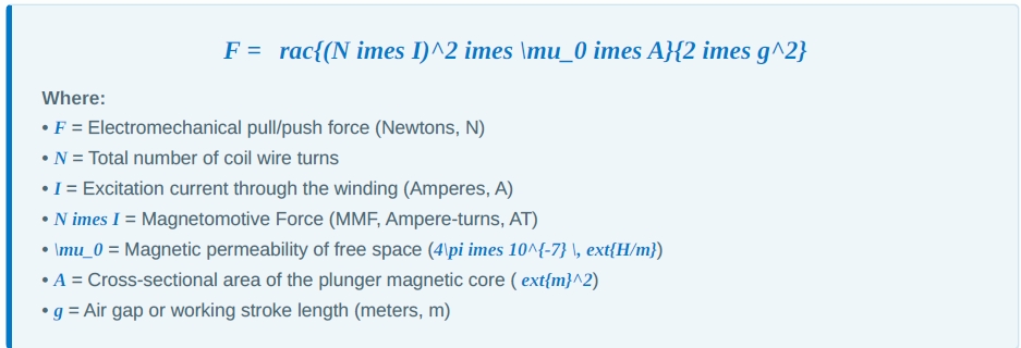
Key Engineering Insight: Notice the inverse-square relationship between force (F) and air gap (g). As the stroke length increases, the force drops off rapidly. Conversely, as the plunger approaches full seating (g o 0), the holding force reaches its maximum potential.
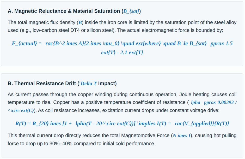
While the simplified formula above works well in ideal conditions, practical solenoid designs must account for magnetic losses and thermal fluctuations:
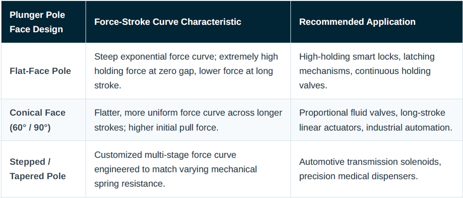
Depending on your mechanical load requirements, Nextcore engineers optimize plunger geometry to shape the force curve:
Nextcore Electronic Co., Ltd. serves tier-1 system integrators and OEM engineers across North America, Western Europe, and Asia-Pacific. We bridge the gap between initial force calculations and mass-produced electromagnetic reliability:
- FEM Magnetic Simulation: We run 2D/3D Finite Element Method (FEM) software to model flux leakage, saturation points, and dynamic stroke-force mapping before tooling creation.
- Custom Thermal Insulation: We engineer Class F (155°C) and Class H (180°C) coil assemblies to handle high duty cycles and elevated ambient temperatures.
- Empirical Verification & Testing: Every custom design is validated on automated force-stroke test benches, producing full empirical force curves for customer design reviews.

We want to give you 10% discount for your first order,
Use discount code at checkout


We want to give you 10% discount for your first order,
Use discount code at checkout